A fall protection system works only if its parts are designed together: the anchor, the line, the energy absorber, the connection to the worker and the structure behind it. This article explains the engineering principles behind that design, including anchorage, fall clearance, swing falls, energy absorption and verification, in plain terms for facility owners, consultants and safety managers.
Written by: Yatin Chaudhary, TsaF.
What does “engineered” mean for a fall protection system?
Short answer: an engineered system has been designed for a specific structure and use. Its anchor loads, fixing method, number of users, fall clearance and compatible components have been worked out, tested to recognised standards and recorded in a design file. A system assembled from parts without that work has no verified performance.
Anchorage: where the load goes
When a worker falls, the arrest force travels from the harness through the connector and lanyard or arrestor into the anchor device, and from there into the host structure. Each link must carry the load.
- Anchor devices are covered by standards such as EN 795:2012, which defines types including single anchors (Type A), transportable anchors (Type B), flexible horizontal lines (Type C), rigid horizontal rails (Type D) and deadweight anchors (Type E). CEN/TS 16415:2013 adds requirements for anchor devices used by more than one person at the same time. In India, the IS 3521 series covers personal fall arrest systems, including Part 7 for single-point anchor devices.
- Fixings must suit the substrate. Trapezoidal sheets, standing-seam roofs, concrete and steel each need a different fixing that has been tested for that material.
- Host structure: purlins, steel members or concrete must be able to take the anchor loads. For flexible horizontal lines, the end anchors see much higher loads than the arrest force on the worker, because a tensioned cable converts a downward pull into a large horizontal force at its ends. This is why end anchors and their fixings receive the closest design attention.
Rigid and flexible anchor lines
| Feature | Flexible line (cable) | Rigid line (rail) |
|---|---|---|
| Examples | Horizontal cable lifeline; rope-type vertical lifeline; overhead cable lifeline | Rail-type vertical lifeline; rigid overhead rail |
| Behaviour in a fall | Deflects (sags), which adds to the fall distance and raises end-anchor loads | Very little deflection |
| Energy absorption | Usually an in-line energy absorber plus the worker’s own absorber | Usually in the trolley or the worker’s connection |
| Typical standards | EN 795 Type C; EN 353-2 for vertical flexible lines | EN 795 Type D; EN 353-1 for vertical rigid lines |
Fall clearance: the space a fall needs
Fall clearance is the clear vertical distance needed below the worker’s feet so that a fall is stopped before they strike the ground, a lower level or equipment. It is the single most important check for any fall-arrest system and the one most often missed.
The required clearance is built up from several components:
- Free fall distance: how far the worker drops before the system starts to act. This depends on the anchor position relative to the harness attachment point and the lanyard length. An anchor above the worker reduces free fall.
- Deceleration distance: how far the energy absorber extends while it slows the fall.
- Lifeline deflection: how far a flexible line sags under load. This depends on span, pre-tension and the number of people on the line.
- Harness stretch and D-ring shift: movement of the harness as it takes the load.
- Height of the worker below the attachment point.
- Safety margin to allow for variation.
Manufacturers publish component values for their products, and the designer adds them for the actual layout. TsaF engineers calculate project-specific clearance during design using the values for the components selected. Where clearance is limited, the usual options are fall restraint, an overhead anchor, a shorter connection or a retractable fall arrestor.
Swing falls and pendulum hazards
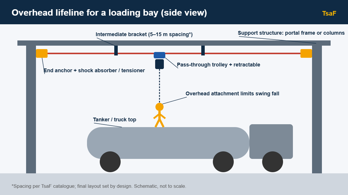
If a worker falls while positioned to one side of the anchor, they swing like a pendulum. They can strike columns, plant or the building edge, and the swing also increases the vertical distance travelled. Swing-fall risk is reduced by:
- using a continuous lifeline that follows the work route, so the anchor point travels with the worker;
- keeping the working zone within a limited angle of the anchor;
- adding intermediate or corner anchors where a route changes direction;
- considering restraint where the edge is close.
Energy absorption
The body can tolerate only limited force during an arrest. Personal fall arrest standards limit the arrest force transmitted to the worker, typically to 6 kN. Energy absorbers achieve this by tearing, deforming or slipping in a controlled way. In a cable lifeline, an in-line shock absorber or tensioner can also reduce the peak load on the end anchors. For example, TsaF’s TSAF-100A combines tensioning with energy absorption on its horizontal lifeline system.
Once an energy absorber has deployed in a fall, it must be replaced, and the whole system should be inspected before it is used again.
Worker movement along the system
A system that forces workers to unclip and re-clip leaves moments without protection. Pass-through trolleys or travellers glide past intermediate brackets, so the worker stays connected along the full route. On overhead lifelines, the choice is between pass-through and non-pass-through trolleys, and whether to add a retractable arrestor to keep slack to a minimum.
Component compatibility
Harnesses, connectors, lanyards, arrestors and anchor lines from different makers may not work safely together. A karabiner can roll out under side loading, or an arrestor may not suit a given rope diameter. Use components that the system manufacturer has tested together, or have a competent person assess compatibility. Connectors and harnesses are covered by standards such as EN 362, EN 361 and IS 3521 Part 5 and Part 1.
Design verification and documentation
Before handover, an engineered system should be supported by:
- a layout drawing showing anchors, spans, corners, access points and user limits;
- a design calculation for anchor loads and fall clearance;
- test certificates for the anchor system and components to the stated standards;
- installation records, including fixing details and any pull tests carried out;
- user instructions, a rescue plan and an inspection schedule.
This file is what an auditor, client or inspector will ask for, and it is the basis of every later inspection.
Frequently asked questions
Why are end-anchor loads so high on a cable lifeline?
A tensioned cable pulled down at mid-span acts like a shallow V. The flatter the V, the larger the horizontal pull at each end. That is why cable lifelines use energy absorbers, why spans and sag are calculated, and why end anchors need robust fixings.
Can I reduce fall clearance by using a shorter lanyard?
Sometimes. A shorter connection or an anchor positioned above the worker reduces free fall. A retractable fall arrestor can also reduce the distance fallen. The right solution depends on the task and must be checked for the full layout.
Does every anchor need a test?
Anchor products should be type-tested to the relevant standard. Installed anchors may also need site verification, such as pull tests on fixings, depending on the substrate and the manufacturer’s instructions.
How many people can use one lifeline?
Only the number stated in the design and handover documents. Adding users increases deflection and anchor loads, so it cannot be changed without re-engineering.
Next step
If you are planning a new installation or checking an existing one, start with the design file. Explore TsaF’s fall protection systems built for Indian sites, or speak to our system design and engineering team.